What is the FUJI KR concept ring arrangement?
KR CONCEPT or “ KR Concept ” is a set of rules and recommendations from Fuji that manufacturers of spinning rods should use to make the most of the properties of guides.
Some rules for placing guides on the rod blank were taken from the old NEW GUIDE CONCEPT (NGC). But there is one very significant difference between these two concepts. If NEW GUIDE CONCEPT is suitable for many series of guide rings intended for spinning rods, then for KR CONCEPT only rings of certain series are suitable. The KR concept arose due to the increased popularity of thin braided cords, which went well with light and small guides (Fig. 1).
Terms:
Choke point – a conditional intersection where the line that passes through the spool axis intersects with the rod blank;
Choke rings are rings that help dampen fishing line vibrations. Placed between Butt and Choke point;
Butt ring – the first ring from the reel;
Runnings or running rings are a series of small rings at the top of the fishing rod.
Fig.1. Comparison of NG Concept and KR Concept
Arrangement of rings on a “long-range” feeder rod. Part 2.
HomeArticlesAll articlesArticle
Fedorov
Rice. 1
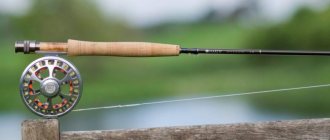
I was not going to write this part because in the first part I set the task of showing how to calculate the location of the first (input, bottom) ring. This is important because the initial data for any arrangement of rings on any rod are its length and the distance from the input ring to the tulip. That's why I drew the reader's attention to calculating the position of this ring. But the manufacturer decides how to arrange the remaining rings himself. There are several such methods. All of them pursue two goals - to evenly distribute the load on the form and to extinguish the spiral of the cord. That is, the points at which the rings will be installed are calculated. Taking any branded rod, removing the ring map from it and thinking about it, you can find the formula by which these rings are arranged. (Of course, if they were not placed along a string with knots). To do this, four operations of arithmetic are enough.
After this, a method is selected for extinguishing the spiral of the cord and delivering it to the tulip. This is a “cone” and a “new concept” and all sorts of other concepts, of which there are as many as there are professional rodbuilders. It's just that some methods are better known, others less.
Take from the store two fishing rods with identical characteristics from the same manufacturer and the same price category , but different series, and compare. You will see that while the positions of the input rings are generally the same, the positions of the others and their sizes (and sometimes their numbers) are different. Sometimes rod blanks are painted in different colors. There's nothing to be done - the manufacturer needs an assortment. Then the buyer can snag not one, but a pair, or even better, three almost identical rods. For example, on one rod I have a No. 25 ring second from the bottom, and on the second one a No. 20 ring. On one, the inner diameter of the tulip is 4 mm, on the second – 3 mm. One has 14 rings (without a tulip), the second has 13. Despite the fact that the entrance rings on both are No. 30 (Fig. 2). That is, the rods differ only in the arrangement of the rings.
Rice. 2
And if one rod throws a little further, it is due to a longer handle, and not due to the placement of rings or the color of the blank. Moreover, there is no ideal placement formula. Otherwise everyone would just use it. You can reduce the friction of the line on the guides to a minimum, but this will deteriorate the balance of the rod and vice versa. The only thing we can pay attention to when purchasing is the distance of the input ring from the coil, and the internal diameter of the tulip. It should not be less than ~3 mm, otherwise the shock leader assembly will quickly break. Otherwise, regarding the placement of rings, you have to rely on the professionalism of the manufacturer. The truth will become clear only on the shore.
But Dima Salapin reprimanded me, writing in the comments: “There is not enough continuation for the rest (except the first) rings.” Guilty. I'm correcting myself. I just don’t know who needs it. Unless to the same rodbuilders. However, I respond to criticism.
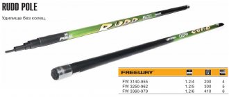
Since the feeder was invented by the British, such standards in the production of rods as length and test are traditionally tied to the English system of weights and measures. That is, to feet, inches and ounces. For example, standard rod lengths are multiples of ~1 foot (~30 cm), and standard test is ~1 ounce (~28 g). According to the rules of feeder building (rodbuilding), the number of rings on the form must correspond to the length of the rod in feet. That is, on a rod with a length of, say, 4.2 m, 14 rings plus a tulip should be installed. Sometimes you come across rods with 13 rings plus a tulip. As a rule, this happens because, during conscientious marking, some ring got into the joint of the knees. Therefore, the markings were made for 13 rings. The British came up with an inertia-free coil, which, due to its design, determines the size of the input ring and the distance to it.
Everything taken together requires a certain arrangement of rings. This scheme, on the one hand, should ensure minimal friction of the cord; on the other hand, to evenly distribute and minimize the load on the form when casting. The abundance of available schemes is due to the fact that an ideal arrangement does not exist. For example, the oldest “cone” pattern provides minimal cord friction, but heavily loads the blank. It has been described inside and out and is still used today. An example is the Carp Pro Torus Carp Feeder series rods.
Let's take as an example a 4.2 m rod with a 60 cm long handle. We plan to use it with a 6000 reel. Therefore, as the lower (input) we will take ring No. 30, say, type Y (on a high leg). In the first part, we calculated that the distance of this ring from the reel should be ~60 cm, and from the butt (taking into account the length of the handle) - 1.2 m. Then, from the input ring to the tulip there remains: 4.2 m - 1.2 m = 3 m. Do you understand? The placement of the rings depends, among other things, on the length of the handle.
We will arrange the rings starting from the tulip. Moreover, each next ring should be 1 inch (~2.5 cm) further from the previous one than the previous one is from its previous one. Oh, I've piled on. In short, if, for example, the first ring is spaced from the tulip by an amount of "x", then the second from the first - (x+2.5 cm), the third from the second - (x+5 cm), the fourth from the third - (x+7 .5 cm). And so on. In this case, all 14 rings must be placed on the remaining three meters. We count:
x+(x+2.5 cm)+(x+5 cm)+(x+7.5 cm)+(x+10 cm)+(x+12.5 cm)+(x+15 cm)+ (x+17.5 cm)+(x+20 cm)+(x+22.5 cm)+(x+25 cm)+(x+27.5 cm)+(x30 cm)+
(x+32.5 cm) = 14x+227.5 cm = 300 cm.
Hence: x = (300-227.5): 14 = 5.2 cm. And this is nothing more than the distance from the tulip to the top ring. Then the formula for arranging tulip rings is: 5 cm ÷ 7.5 cm ÷ 10 cm ÷ 12.5 cm ÷ 15 cm ÷ 17.5 cm ÷ 20 cm ÷ 22.5 cm ÷ 25 cm ÷ 27.5 cm ÷ 30 cm ÷ 32.5 cm ÷ 35 cm ÷ 37.5 cm. Take a felt-tip pen and... go ahead and make markings on the rod. If some ring gets on the edge of the joint, it can be placed so that the braid of the joint is also the braid of the ring. Or move it a couple of centimeters. And at the same time move the neighbors a little. There won't be a big problem. If you need to move far, you can try to calculate the arrangement for 13 rings. Perhaps this arrangement will be perfect. If I'm not mistaken, the author of this scheme is the famous rodbuilder Kirkman. As you can see, if you approach the issue professionally, you can do without ropes and knots.
Now (as an option) we select rings, starting with input number 30. Next: No. 25, No. 20, No.!6, No. 12, No. 10 No. 8. then 3 rings No. 7 and 4 rings No. 6. The tulip is the same size. All. We have described only one of the existing methods. But there are others.
In conclusion, I note that the number of rings on a form of any length was determined a long time ago and does not cause disagreement. The difference between one arrangement method and another is only in the criterion or coefficient we chose to determine the distance from one ring to another.
Tags: feeder theory
2
Register or log in to comment.
Stepanych
-> Article
Arrangement of rings on a “long-range” feeder…
14.01.2021 07:37:25
The formula is correct. But then it’s a little different. Rings are usually designed for a specific reel and a specific form. The intersection of the centerline of the reel with the blank does not coincide with the end of the blank. As a rule, a ring called a “chok” is placed at the place of suppression. Ideally, the choke should be located at a certain point. If you take the blank in your hands in a horizontal position, holding it with your hand in the area of the reel seat, and lightly hit the end of the handle with your other hand in a horizontal position, the blank will begin to vibrate, but the “choke” should remain motionless. Calculations are made from the reel seat to the choke. After the choke, the rings are usually set to the same size.
Fedorov
-> Article
Arrangement of rings on a “long-range” feeder…
14.01.2021 15:11:19
Maybe. I'm not involved in rollbuilding, so I won't argue. But in my (possibly erroneous) understanding, the choke is the last ring that is involved in damping the cord spiral. And we put it where we need it. The closer the choke, the greater the total friction on the rings, but the less the load on the rod blank. And vice versa. Using the formula given in the first part, we can calculate that the center line of the 6000th reel intersects with the axis of the rod at a distance of ~110cm from the reel. Or 40÷50cm from the entrance ring (depending on its height). This is the minimum possible distance to the choke. That is, in principle, the second ring from the bottom can be the choke. Another question is how practical this is. And the maximum possible distance is when the choke is a tulip. This arrangement is called “cone”.
Key Features of the FUJI KR Concept
- The height of the legs of the first rings from the reel plays an important role in this concept. In the KR concept, smaller diameter first rings from the reel are used to quickly dampen the rotating cone and better control of the line when casting. But in this case, the arc of vibration of the fishing line between the first rings increases, which theoretically can lead to the fishing line touching the blank. To prevent this, make the legs of the throughput rings higher and increase their number.
- As a result of the rapid damping of the cone, the line stops oscillating faster. This property allows us to move the Chock closer to the coil, but thereby we will need to increase the number of runners that go behind it. What are the benefits of this? With this arrangement of rings, the line is pulled out earlier into a straight line along the blank when casting. This will give us greater sensitivity of the tackle and increase casting distance and accuracy, and adding one running rod adds some power. Fuji calls this process “Rapid Choke,” which literally means “rapid choke.” To make this process more efficient, KR-series rings are designed so that the plane of the ring mandrel is at an angle of 300 to its frame.
- The displacement of relatively powerful Choke rings towards the reel leads to an increase in the load on the spinning blank in the middle part, where low-power running rods are located. To remove this “misunderstanding”, special rings of the KB series are placed in this place.
What rings are used in the FUJI KR Concept
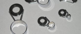
FUJI KR Concept spinning rods use three types of guide rings - KL-H, KB, KT .
KL-H guide rings (Fig. 2) are used as Butt rings to quickly dampen fishing line vibrations. The design of the frame is made “without corners”, so that there is nothing for the fishing line to cling to. The series has a smaller insert diameter. The index “H” indicates that this ring has a high stem. Currently available sizes: 25, 20, 16, 12, 10, 8, 5.5mm.
Fig.2. Rings KL-H
KB series guide rings (Fig. 3) is to relieve the load on the blank in the middle part of the rod. To counteract the load, these rings have wide and powerful legs and a thick mandrel. The frame design is also made in a “no corners” design. Depending on the length of the spinning rod, from one to three KB series rings are used. Available in sizes 4, 4.5 mm.
Fig.3. KB rings
For running rings, KT (Fig. 4). They are characterized by very light weight due to the thin frame and mandrel. They have the same “no corners” design. Light weight allows you to relieve the thin upper part of the rod. They have sizes: 4, 4.5, 5, 5.5, 6, 8, 10mm.
Fig.4. KT rings
Arrangement of rings on spinning rods according to FUJI KR Concept
Note:
Above the form is the distance between the rings in cm. Below the form is the diameter of the passage rings in mm and their markings.
Spinning 183cm
The total length of the rod is 6′ (183cm), number of rings – 8 pcs:
Spinning 198cm
Spinning 213cm
The total length of the rod is 7′ (213cm), the number of rings is 10 pcs:
Spinning 229cm
The total length of the rod is 7'6" (229cm), number of rings - 10 pcs:
Spinning 244cm
The total length of the rod is 8′ (244cm), the number of rings is 11 pcs:
Spinning 260cm
The total length of the rod is 8'6" (260cm), number of rings - 11 pcs:
Spinning 275cm
The total length of the rod is 9′ (275cm), the number of rings is 11 pcs:
Correct placement of rod guides
The productivity of the catch is affected by the number of passers. Their correct location ensures uniform distribution of the load along the entire length of the form.
The fewer rings, the easier it is to make a long cast, but the likelihood of the rod breaking increases. The passage elements should be located along the inner seam of the whip, in one line.
To avoid various troubles during the fishing process, you need to correctly arrange the rings:
- quantity 6-7 pcs.;
- The gap between the products towards the top of the form increases by 0.2 mm.
The principle of arrangement of passage parts
There are 2 common methods of arrangement:
- Traditional - several elements are taken and arranged in the form of a cone-shaped tunnel. In this case, the first ring is the base, the last one serves as the top of the entire structure.
- New - the cone is reduced due to the displacement of the first part to the central part of the structure. The base line is passed through the small elements.
To check the work done, bend the rod so that all components are combined. Then all errors are immediately visible.
Arrangement of rings