Do-it-yourself echo sounder for fishing
Homemade items from a washing machine motor:
1. How to connect a motor from an old washing machine through or without a capacitor 2. Homemade emery from a washing machine motor 3. Homemade generator from a washing machine motor 4. Connecting and adjusting the speed of a commutator motor from a washing machine - automatic 5. Potter's wheel from a washing machine 6. Lathe from an automatic washing machine 7. Wood splitter with an engine from a washing machine 8. Homemade concrete mixer
Homemade mini-echo sounder on Atmel ATMega8L microcontroller
And
LCD from mobile phone nokia3310
I present to your attention my author’s development - a homemade mini-echo sounder on an Atmel ATMega8L microcontroller and an LCD from a nokia3310 mobile phone. The device is designed to be replicated by an average-skilled radio amateur, but I think anyone can replicate the design. I tried to present the material in such a way as to give readers more useful information on the topic in an accessible form. I hope that repeating the design will bring you a lot of pleasure and benefit.
I will be glad to answer your questions/wishes/comments and help in repeating the design.
Best regards, Alex
Echo sounder, sonar - short for SOund NAvigation and Ranging. Echo sounders have been around since the 40s, and the technology was developed during World War II to track enemy submarines. In 1957, Lowrance released the world's first transistorized fish finder for sport fishing.
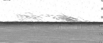
The echo sounder consists of the following main functional blocks: microcontroller, transmitter, emitter sensor, receiver and display. The process of detecting the bottom (or fish) in a simplified form is as follows: the transmitter emits an electrical impulse, the emitter sensor converts it into an ultrasonic wave and sends it into the water (the frequency of this ultrasonic wave is such that it is not felt by either humans or fish). The sound wave is reflected from an object (bottom, fish, other objects) and returns to the sensor, which converts it into an electrical signal (see figure below).
The receiver amplifies this returned signal and sends it to the microprocessor. The microprocessor processes the signal received from the sensor and sends it to the display, where we already see an image of objects and the bottom topography in a form convenient for us.
What you should pay attention to: the echo sounder draws bottom relief only in motion. This statement follows from the principle of operation of the echo sounder. That is, if the boat is stationary, then the information about the bottom topography is unchanged, and the sequence of values will consist of identical, absolutely identical values. A straight line will be drawn on the screen.
The first question that I am sure will arise from readers is “Why is such a small display used?” Therefore, I will answer it right away: this “mini-echo sounder” was developed at the request of a friend from what was at hand. And these available means turned out to be ATMega8L, a display from nokia3310 and some kind of emitter with the designation f=200kHz. You may also be asking, is it possible to remake the program/circuit for another, larger display? Yes. Theoretically this is possible.
My design differs from the echo sounders described in [1, 2, 3] by the use of a graphic LCD display, which gives the device advantages in displaying useful information.
The entire structure is assembled in the “Z14” housing. Power is provided from a 9V GP17R9H battery. The maximum current consumption is no more than 30 mA (in the author's version 23 mA).
Now about the capabilities of the echo sounder. The operating frequency is 200 kHz and is adjusted to the specific existing emitter. The ability to measure depths up to 99.9 meters is implemented in software. But I’ll say right away: the maximum depth that an echo sounder can “see” will largely depend on the parameters of the emitter used. At this time, my design was tested only on a reservoir with a maximum depth of about 4 m. The device showed excellent results. Whenever possible, I will try to test the operation of the echo sounder at greater depths, which will be reported to readers.
So, let's move on to the diagram. The mini echo sounder circuit is shown in the figure below:
The main functional blocks of the echo sounder: control circuit (that is, the ATMega8L microcontroller), transmitter, emitter, receiver, display, keyboard, battery charging circuit.
The echo sounder operates as follows: the microcontroller at pin PB7 generates a control signal (rectangular pulses log. “0”) with a duration of approximately 40 μs. This signal starts the master oscillator with an operating frequency of 400 kHz on the IC4 chip for a specified time. Next, the signal is fed to the IC5 chip, where the signal frequency is divided by 2. The signal from IC5 is fed to the buffer stage on the IC6 chip and then to the Q3 and Q4 switches. Next, the signal from the secondary winding of transformer T1 is fed to the piezoceramic sensor-emitter LS2, which sends ultrasonic messages to the external environment.
The signal reflected from the bottom/obstacle is received by the emitter sensor and fed to the input of the receiver, which is assembled on the SA614AD microcircuit in a typical connection (see Datasheet on SA614AD). The BAV99 diode assembly at the receiver input limits the input voltage of the receiver while the transmitter is operating.
The signal from the receiver is fed to a comparator on the LM2903 chip, the sensitivity of which is controlled by the microcontroller.
Next, the signal is processed in the microcontroller and displayed in the required form on an 84x48 pixel graphic LCD display.
The transmitter transformer T1 is wound on a K16*8*6 core made of M1000NM ferrite. The primary winding is wound in 2 wires and contains 2x14 turns, the secondary winding is 150 turns of PEV-2 0.21mm wire. The secondary winding is wound first. The halves of the primary winding must be “stretched” along the entire length of the core. The windings must be insulated from each other with a layer of varnished cloth or transformer paper.
Now the most interesting and problematic part: the emitter sensor. This problem was solved for me initially: I already had a ready-made emitter. What should you do? Option 1: purchase a ready-made sensor. Option 2: make it yourself from TsTS-19 piezoceramics.
When flashing the ATMega8L microcontroller firmware, set the fuse bits according to the picture below:
Complete information on manufacturing, configuration, firmware and instructions for using a mini echo sounder
look in the attached archive!
Do-it-yourself echo sounder from a smartphone
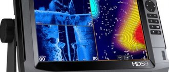
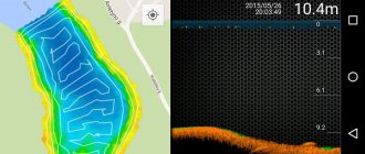
Portable models of echolocators allow you to connect a sensor emitting an ultrasonic wave directly to a gadget, be it a phone, tablet or laptop. The peculiarity of such devices is their simplicity and wireless connection. They work directly via Wi-Fi or Bluetooth. For the device to work, you need to download a free application and lower the sensor into the water. When it comes into contact with water, it automatically turns on and begins to display relevant information on the smartphone display.
The cost of such a sensor is around 4 thousand rubles, but in terms of functionality it is almost not inferior to expensive analogues.
Connecting such a device yourself does not cause any difficulties. Just follow the instructions or watch a video on how to connect an echo sounder with your own hands.
Source
Do-it-yourself echo sounder for fishing
for this circuit
The main functional blocks of the echo sounder: control circuit (that is, the ATMega8L microcontroller), transmitter, emitter, receiver, display, keyboard, battery charging circuit.
The echo sounder operates as follows: the microcontroller at pin PB7 generates a control signal (rectangular pulses log. “0”) with a duration of approximately 40 μs. This signal starts the master oscillator with an operating frequency of 400 kHz on the IC4 chip for a specified time. Next, the signal is fed to chip IC5, where the signal frequency is divided by 2. The signal from IC5 is fed to the buffer stage on chip IC6 and then to switches Q3 and Q4, the load of which is transformer T1. The signal from the secondary winding of transformer T1 is fed to the piezoceramic sensor-emitter LS2, which sends ultrasonic messages to the external environment.
Do-it-yourself echo sounder for an amateur fisherman.
A block diagram explaining the structure and operation of the echo sounder is shown in Fig. 1. Clock generator G1 controls the interaction of the device components and ensures its operation in automatic mode. The short (0.1 s) rectangular pulses of positive polarity generated by it are repeated every 10 s. With their front, these pulses set the digital counter PC1 to the zero state and close the receiver A2, making it insensitive to signals while the transmitter is operating.
At the end of the transmitter operation, the A2 receiver opens and acquires normal sensitivity. The echo signal reflected from the bottom is received by sensor BQ1 and, after amplification in the receiver, closes key S1. The measurement is completed and the PC1 counter indicators display the measured depth. The next clock pulse again resets the PC1 counter to zero, and the process repeats.
The schematic diagram of an echo sounder with a depth measurement limit of up to 59.9 m is shown in Fig. 2. Its transmitter is a push-pull generator on transistors VT8, VT9 with transformer T1 tuned to the operating frequency. The positive feedback necessary for self-excitation of the generator is created by circuits R19C9 and R20C11.
The generator generates pulses with a duration of 40 μs with radio frequency filling. The operation of the transmitter is controlled by a modulator consisting of a single-vibrator on transistors VT11, VT12, which generates a modulating pulse with a duration of 40 μs, and an amplifier on transistor VT10. The modulator operates in standby mode, the triggering clock pulses arrive through capacitor C14.
The echo sounder receiver is assembled using a direct amplification circuit. Transistors VT1, VT2 amplify the echo signal received by the emitter-sensor BQ1, transistor VT3 is used in the amplitude detector, transistor VT4 amplifies the detected signal. A single-vibrator is assembled on transistors VT5, VT6, ensuring constancy of the parameters of the output pulses and the sensitivity threshold of the receiver. The receiver is protected from the transmitter pulse by a diode limiter (VD1, VD2) and resistor R1. The receiver uses forced switching off of the receiver's monostable using transistor VT7. A positive clock pulse is sent to its base through diode VD3 and charges capacitor C8. When opening, transistor VT7 connects the base of transistor VT5 of the receiver monostable with the positive power wire, thereby preventing the possibility of it being triggered by incoming pulses. At the end of the clock pulse, capacitor C8 is discharged through resistor R18, transistor VT7 gradually closes, and the monostable receiver acquires normal sensitivity. The digital part of the echo sounder is assembled on DD1-DD4 microcircuits. It includes a key on element DD1.1, controlled by an RS trigger on elements DD1.3, DD1.4. The counting start pulse comes to the trigger from the transmitter modulator through transistor VT16, the end pulse comes from the receiver output through transistor VT15. A pulse generator with an exemplary repetition frequency (7500 Hz) is assembled on the DD1.2 element. Resistor R33 and coil L1 form a negative feedback circuit that brings the element to the linear portion of the characteristic. This creates conditions for self-excitation at a frequency determined by the parameters of the L1C18 circuit. The generator is tuned exactly to a given frequency using a coil trimmer. The reference frequency signal is fed through the switch to a three-digit counter DD2-DD4. It is set to the zero state by the edge of the clock pulse supplied through the diode VD4 to the inputs R of the microcircuits. The clock generator that controls the operation of the echo sounder is assembled using transistors of different structures VT13, VT14. The pulse repetition rate is determined by the time constant of the R28C15 circuit. The cathodes of the indicators HG1-HG3 are powered by a generator using transistors VT17, VT18 [2]. Button SB1 (“Control”) is used to check the functionality of the device. When you press it, the VT15 key receives a closing pulse and the echo sounder indicators display a random number. After some time, a clock pulse switches the counter, and the indicators should display the number 888, which indicates that the echo sounder is working.
ECHO SOUNDER FOR AN AMATEUR FISHER
» Catalog of circuit diagrams » For home and everyday lifeA block diagram explaining the structure and operation of the echo sounder is shown in Fig. 1. Clock generator G1 controls the interaction of the device components and ensures its operation in automatic mode. The short (0.1 s) rectangular pulses of positive polarity generated by it are repeated every 10 s. With their front, these pulses set the digital counter PC1 to the zero state and close the receiver A2, making it insensitive to signals while the transmitter is operating. The falling clock pulse triggers the transmitter A1, and the emitter-sensor BQ1 emits a short (40 μs) ultrasonic probing pulse in the direction of the bottom. At the same time, the electronic key S1 opens, and oscillations of a reference frequency of 7500 Hz from the generator G2 are sent to the digital counter PC1.
Puc.1
At the end of the transmitter operation, the A2 receiver opens and acquires normal sensitivity. The echo signal reflected from the bottom is received by sensor BQ1 and, after amplification in the receiver, closes key S1. The measurement is completed and the PC1 counter indicators display the measured depth. The next clock pulse again resets the PC1 counter to zero, and the process repeats.
The schematic diagram of an echo sounder with a depth measurement limit of up to 59.9 m is shown in Fig. 2. Its transmitter is a push-pull generator on transistors VT8, VT9 with transformer T1 tuned to the operating frequency. The positive feedback necessary for self-excitation of the generator is created by circuits R19C9 and R20C11.' The generator generates pulses with a duration of 40 μs with radio frequency filling. The operation of the transmitter is controlled by a modulator consisting of a single-vibrator on transistors VT11, VT12, which generates a modulating pulse with a duration of 40 μs, and an amplifier on transistor VT10. The modulator operates in standby mode, the triggering clock pulses arrive through capacitor C14.
Puc.2
The echo sounder receiver is assembled using a direct amplification circuit. Transistors VT1, VT2 amplify the echo signal received by the emitter-sensor BQ1, transistor VT3 is used in the amplitude detector, transistor VT4 amplifies the detected signal. A single-vibrator is assembled on transistors VT5, VT6, ensuring constancy of the parameters of the output pulses and the sensitivity threshold of the receiver. The receiver is protected from the transmitter pulse by a diode limiter (VD1, VD2) and resistor R1.
The receiver uses forced switching off of the receiver's monostable using transistor VT7. A positive clock pulse is sent to its base through diode VD3 and charges capacitor C8. When opening, transistor VT7 connects the base of transistor VT5 of the receiver monostable with the positive power wire, thereby preventing the possibility of it being triggered by incoming pulses. At the end of the clock pulse, capacitor C8 is discharged through resistor R18, transistor VT7 gradually closes, and the monostable receiver acquires normal sensitivity. The digital part of the echo sounder is assembled on DD1-DD4 microcircuits. It includes a key on element DD1.1, controlled by an RS trigger on elements DD1.3, DD1.4. The counting start pulse comes to the trigger from the transmitter modulator through transistor VT16, the end pulse comes from the receiver output through transistor VT15.
A pulse generator with an exemplary repetition frequency (7500 Hz) is assembled on the DD1.2 element. Resistor R33 and coil L1 form a negative feedback circuit that brings the element to the linear portion of the characteristic. This creates conditions for self-excitation at a frequency determined by the parameters of the L1C18 circuit. The generator is tuned exactly to a given frequency using a coil trimmer.
The reference frequency signal is fed through the switch to a three-digit counter DD2-DD4. It is set to the zero state by the edge of the clock pulse supplied through the diode VD4 to the inputs R of the microcircuits.
The clock generator that controls the operation of the echo sounder is assembled using transistors of different structures VT13, VT14. The pulse repetition rate is determined by the time constant of the R28C15 circuit.
The cathodes of the indicators HG1-HG3 are powered by a generator using transistors VT17, VT18 [2].
Button SB1 (“Control”) is used to check the functionality of the device. When you press it, the VT15 key receives a closing pulse and the echo sounder indicators display a random number. After some time, a clock pulse switches the counter, and the indicators should display the number 888, which indicates that the echo sounder is working.
The echo sounder is mounted in a box glued together from impact-resistant polystyrene. Most of the parts are placed on three printed circuit boards made of foiled fiberglass laminate with a thickness of 1.5 mm. The transmitter is mounted on one of them, the receiver on the other, and the digital part of the echo sounder on the third. The boards are fixed on a duralumin plate measuring 172x72 mm, inserted into the lid of the box. In the plate and cover, holes are drilled for the power switch Q1 (MT-1), the SB1 button (KM1-1) and the VR-74-F socket of the coaxial connector XI, and a window for digital indicators is also cut out.
The echo sounder uses MLT resistors, KLS, KTK and K53-1 capacitors. Transistors KT312V and GT402I can be replaced with any other transistors of these series, MP42B with MP25, KT315G with KT315V. Microcircuits of the K176 series are interchangeable with the corresponding analogues of the K561 series; instead of the K176IEZ (DD4) microcircuit, you can use K176IE4. If the echo sounder will be used at a depth of no more than 10 m, the DD4 counter and the HG3 indicator do not need to be installed.
The windings of transformer T1 are wound with PELSHO wire 0.15 on a frame with a diameter of 8 mm with a ferrite (600NN) trimmer with a diameter of 6 mm. Winding length - 20 mm. Winding I contains 80 turns tapped from the middle, winding II contains 160 turns. Transformer T2 is made on a ferrite (3000NM) ring of standard size K16X10X4.5. Winding I contains 2X 180 turns of PEV-2 wire, 0.12, winding 11-16 turns of PEV-2 wire, 0.39. Coil L1 (1500 turns of PEV-2 0.07 wire) is wound between the cheeks on a frame with a diameter of 6 mm made of organic glass. The diameter of the cheeks is 15, the distance between them is 9 mm. The trimmer is from the SB-1a armored magnetic circuit made of carbonyl iron.
The ultrasonic emitter-sensor of the echo sounder is made on the basis of a round plate with a diameter of 40 and a thickness of 10 mm made of barium titanate. Thin (0.2 mm in diameter) lead conductors are soldered to its silver-plated planes using Wood's alloy. The sensor is assembled in an aluminum cup from an oxide capacitor with a diameter of 45...50 mm (height - 23...25 mm - specified during assembly). In the center of the bottom of the glass, a hole is drilled for a fitting through which a coaxial cable (RK-75-4-16, length 1...2.5 m) will enter, connecting the sensor to the echo sounder. The sensor plate is glued with 88-N glue to a disk made of soft microporous rubber 10 mm thick.
During installation, the cable braid is soldered to the fitting, the central conductor is soldered to the terminal of the sensor plate glued to the rubber disk, and the terminal of the other plate is soldered to the cable braid. After this, the disk with the plate is pushed into the glass, passing the cable into the opening of the fitting, and the fitting is secured with a nut. The surface of the titanium plate should be recessed into the glass 2 mm below its edge. The glass is fixed strictly vertically and filled to the edge with epoxy resin. After the resin has cured, the surface of the sensor is sanded with fine-grit sandpaper until a smooth surface is obtained. The mating part of connector XI is soldered to the free end of the cable.
To set up an echo sounder, you need an oscilloscope, a digital frequency meter and a 9 V power supply. After turning on the power, check the functionality of the counting device: if it is working properly, the indicators should display the number 88.8. When you press the SB1 button, a random number should appear, which, with the arrival of the next clock pulse, should again be replaced by the number 88.8.
Next, the transmitter is set up. To do this, a sensor is connected to the echo sounder, and an oscilloscope operating in the standby sweep mode is connected to winding 11 of transformer T1. With the arrival of each clock pulse, a pulse with radio frequency filling should appear on the oscilloscope screen. By adjusting transformer T1 (if necessary, select capacitor C10) the maximum pulse amplitude is achieved, which should be at least 70 V.
The next stage is the establishment of a pulse generator of exemplary frequency. To do this, the frequency meter is connected through a resistor with a resistance of 5.1 kOhm to pin 4 of the DD1 microcircuit. The generator is tuned to a frequency of 7500 Hz by adjusting coil L1. If the trimmer occupies a position far from the average, select capacitor C18.
The receiver (as well as the modulator) is best tuned based on echo signals, as described in
What is a fishing depth gauge?
The main key to success on any body of water is how correctly and carefully the angler determines the depth at the fishing spot. The competent choice of a specific point for casting the equipment, its features and other technical nuances that affect the effectiveness of fishing depend on this. Since ancient times, a fishing depth gauge has been used for these purposes, allowing it to solve the problem.
Devices for determining the depth and topography of the bottom are used all year round. They are used from ice or in open water, and you can take measurements with them while in a boat or on the shore. Various options for depth gauges allow the fisherman to choose the optimal modification for a specific situation and his own preferences in order to feel as comfortable and at ease as possible during the fishing process.
What types of depth gauges are there?
Depth gauge is a device designed to measure depth and changes in bottom topography in a given water area. With its help, you can detect various anomalous zones in the fishing area and determine the most potentially promising points where you should send the equipment. It helps to find dumps, grooves, hills, local tubercles, pits and other characteristic places for fish.
You can make depth gauges for fishing yourself or purchase them in a store. A homemade product is cheap, simple and reliable. The factory one is more expensive, but you don’t have to waste time making it. The most modern device for measuring depth is an echo sounder. Today it is the one that is in greatest demand and is used by many fishermen.
DIY depth gauge
The simplest solution to purchasing a depth gauge for fishing is to make it yourself at home. This device is easy to make from scrap materials. Today, the following types of these devices are common among fishermen:
- from lead pear;
- with float marker;
- made of lead and rubber;
- made of polystyrene foam and lead weight.
Below we will consider some options for making a depth gauge with your own hands, their advantages and features.
With float marker
A simple and reliable design of a depth gauge, which is also very effective on various unfamiliar bodies of water. Step-by-step instructions for making it look like this:
- Take a foam ball or a round float with a load capacity of about 15–20 grams.
- A sinker of the required weight is attached to the fishing line using a swivel. In many cases, 50–60 grams is enough.
Photo 1. Two ounces equals approximately 56 grams.
All. The depth gauge is ready. Now you can start measuring the depth at the fishing spot and determining the bottom topography:
- To begin with, you should put some kind of measurement mark on the rod blank. 50 cm is measured from the line roller and electrical tape is wrapped around the form several times.
Photo 2. Marking with electrical tape.
- Having determined the depth value at the first point, we reel in the fishing line and move the load one to two meters, repeating the measurement procedure.
Thus, we “ring” the entire direction to the shore. Then we cast at different angles and measure the depth. Within half an hour, you can thoroughly study the topography in the fishing zone and identify potentially catchable points.
Made from polystyrene foam and lead weight
This option is also designed for measuring from the shore; its operating principle is similar to the first device. You can make it like this:
- Take a piece of polystyrene foam of rectangular or square shape. We make two mating holes in it, located at an angle of 40–50 degrees to the horizontal axis.
- Insert a used ballpoint pen into the hole.
- The depth measuring line is passed through the rod.
- A lead weight of the required weight is attached to its free end directly or using a swivel.
This depth gauge allows you to very accurately measure depth in still water bodies. On rivers with currents, we obtain values with some error.
Made of lead and rubber
This depth gauge is intended not so much for measuring the fishing area, but rather for determining the location of the bait that is most attractive to the fish. It is used in float or plug fishing, when it is necessary to raise the bait above the bait spot by 3–5 cm, making it more noticeable and more appetizing to the fish. It looks and is made as follows:
- We attach a rectangular piece of rubber to the hook.
- On its other edge we fix a lead weight with a weight capable of drowning the float used.
This simple depth gauge allows you to quickly set up the equipment and position the bait at the optimal distance from the bottom.
Photo 3. Option: silicone and jig head. We hook the hook onto the silicone.
DIY echo sounder
Every fisherman knows that fish in a reservoir are grouped in certain areas where they can hide, sleep, reproduce, and hunt. Typically, their habitat depends on water temperature, underwater currents, and the presence of relief objects under which one can easily hide from danger.
It is impossible to determine exactly where they are with the naked eye. For this purpose, devices are used that make it possible to study the bottom topography and its depth using ultrasonic radiation. Improved models make it possible to identify areas where fish accumulate and mark the most successful catch spots. There are two main types of echo sounders: stationary and portable, which differ in functionality, size and cost.
Such devices greatly simplify the fishing process, but are expensive. To save money, you can make an echo sounder yourself.